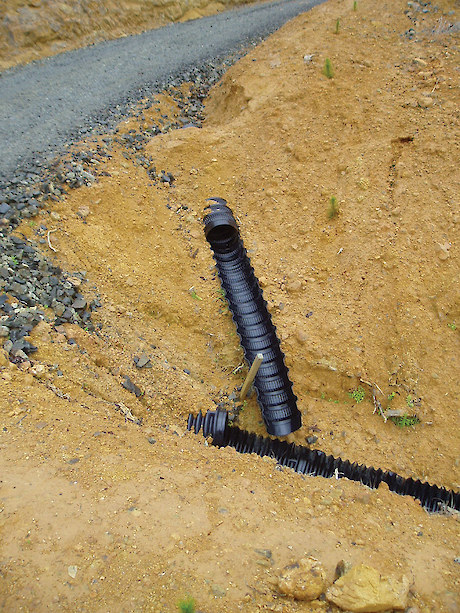
The flume has good fall to reduce silting, is well pegged, and drains into slash to reduce erosion. Ribbed flumes slow water down compared with smooth bored flumes
 The fully flexible pipe is a good option for this exposed locationFlumes help to protect earthworks from erosion by conveying water over vulnerable areas, such as fill and batter slopes, to more stable ground. Most roads in hill country require sections to be flumed. Flumes, like drainage culverts, require fall to reduce silting up. Install flumes at the time of drainage culvert construction.
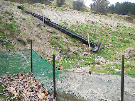
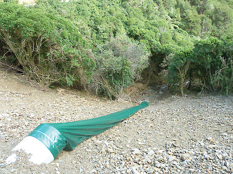
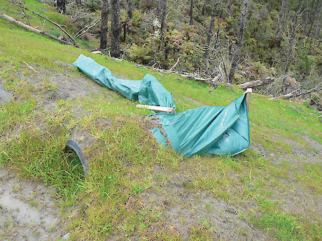
Flumes come in several types. They are often made of half round sections of flexible corrugated material, such as polyethylene half round sections. Flexible flumes are less prone to failure, as they bend to follow the terrain and the corrugations decrease the water speed. Corrugated iron should not be used. Consider using flexible, full round flumes for very windy sites, as they can better withstand windy conditions compared to half round flumes. Culvert sock flumes are an enclosed fabric sock. As their name suggests, the sock flume is pulled over the culvert, and clamped on to the culvert outlet. They can be used where standard fluming would not work effectively, for example, if directing water over long and unstable fills.
 Galvanised iron or tin flumes are not good practice. They increase water speed, and cannot easily follow the terrain. The sheets do not lock together, and can fall apart
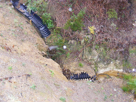
 Rock armouring cut-outs and culvert exits are an effective way to reduce water speed and scouringFlumes can also be used to direct water to additional sediment and stormwater control measures, such as slash and sediment traps. Where the flume discharges to stable ground, still consider slash, rock or half pipe energy dissipation at the outlet to reduce the velocity and energy of the discharge. Where additional sediment control structures are to be used, ensure the flume is located at a suitable site to construct these.
Construct a solid flume entrance that will not be bypassed by storm flow. Inlets to flumes are a common failure point. Ensure the entrance is well compacted and armoured, if necessary. Ensure the flume is anchored and well supported to avoid displacement or separation from the culvert outlet. Make sure that the flume has a minimum slope of 3 %. This will stop the flume from infilling with sediment.
Be careful with culvert sock installation. Secure the sock to the culvert so that water does not undercut or rip off the sock. Ensure the sock has a minimum slope of 5%. This will stop the sock from infilling with sediment. Anchor the sock eyelet and attach it to the ground for its entire length to avoid twisting. Twisting can lead to the sock malfunctioning, and the weight of sediment and water can pull it off the culvert. Consider installing socks upside down, with tie-down points tied up to the holes in steel Y-posts (waratahs), to stop potential rolling in strong wind locations if other installation methods have failed.