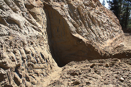
A typical drainage culvert inlet with a sediment trap before it. The trap is deeper than the pipe inlet, and it can easily be cleaned out by an excavatorWater needs to be regularly discharged from a ditch to reduce both water velocity and volume. This is critical on light and weak soil like pumice to minimise scour, and is achieved by the regular placement of road drainage (stormwater) culverts or water cut-outs. A drainage culvert drains water from the inside to the outside of the road where there are no opportunities to direct it off from the inside. If properly designed, constructed and maintained correctly, they will last a rotation and often longer. Culverts used to cross rivers are described in Chapter 8: River crossings.
Drainage culverts are often made of corrugated PVC. Do not use untreated wood or pine logs for permanent drainage culverts. It is good practice to construct a sediment trap immediately before a culvert inlet. Road drainage culvert outlets that drain onto stable, non-modified ground require no additional erosion and sediment controls, although using slash to armour the culvert outlet from potential erosion is good practice. Road drainage culverts may have additional sediment control measures down slope of their outlet, including flumes, sediment traps, soak holes or sediment retention ponds.
The NES-PF’s earthworks stormwater regulations require a road drainage culvert to have a minimum internal diameter of 325 mm in green or yellow zones, and orange zones less steep than 25°, and a minimum internal diameter of 375 mm for NES-PF red zones, and orange zones steeper than 25°.
Recommended maximum spacing (m) for road drainage culverts located on roads traversing mid and lower slopes Space and locate road drainage culverts correctly. The adjacent table provides a guide to appropriate culvert spacing. The suggested maximum spacing relates to soil type and road steepness for roads that traverse across the mid and lower slopes. On roads located on ridge tops or flat/rolling topography, maximum spacing may well be greater than those in the table due to the ditches not intercepting water from the terrain above the road. Where topography makes it difficult to achieve the minimum spacings, consider using larger pipes and rock armouring at culvert inlets and outlets. Culvert outlets are best located on solid ground and not on fill. Also consider the likelihood of culvert blockage and the subsequent risk to other drainage structures. Cut bank collapse can choke the culvert entrance. This can be relatively common on new roads in weak soils or friable/crumbly rock. To reduce the risk of damage to the road, and potentially on-going environmental issues, it may be prudent to consider a higher culvert density and larger sized culverts.
The table shows that the steeper the road and more erodible the geology the closer the culverts need to be placed. Use local knowledge to help refine spacing for specific locations and soil types. Intensity of rainfall should also be considered. A greater frequency of culverts, deeper ditches and larger culvert sizes may be required to address risks.
Avoid drainage culverts that discharge directly into a river or a water body. Where practicable, water should flow over land to filter through slash or natural vegetation before entering the water body. Install road drainage culverts a short distance up gradient of a river crossing. This will help reduce sediment into it.
7.4.1 Drainage culvert location and installation
Culverts need to be correctly located and installed. Where possible, locate culverts to avoid fills so that they can discharge water onto stable ground to reduce sedimentation. Locate drainage culverts away from road corners to reduce damage by vehicles.
The following provides guidelines on installing drainage culverts:
- Culvert pipes should be installed according to the pipe manufacturer’s specifications
- Install road drainage culverts during road construction, and prior to metalling the carriageway
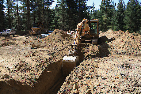
- Preferably, install culverts with an excavator
- Locate on hard ground, and avoid fill
- Set the culvert at a minimum 20° across the road or at the same/similar road grade, unless the road is being drained from two directions
- Ensure there is enough gradient on the culvert. Use a minimum 3% crossfall to reduce the risk of blockage
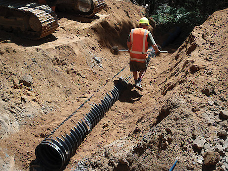
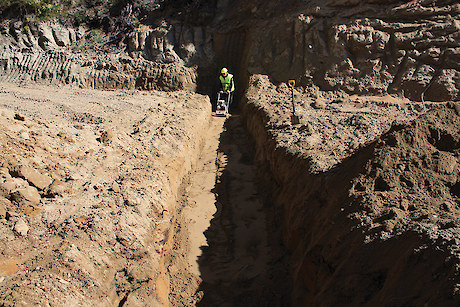
- Ensure the culvert trench base is even and compacted, and running at the correct gradient along its entire length
- Join pipe sections in the trench
- Make sure there are no sharp rocks or objects in backfill that could damage the pipe
- Ensure backfill is compacted in layers. Polyethylene pipe will deform, as its structural integrity relies on the compacted fill
- Where needed, build a solid bund at the culvert inlet to ensure stormwater is directed into the culvert mouth, and does not bypass the culvert
- Construct culvert inlets with associated silt traps so they are easy to clean out with an excavator. Make sure the dimensions allow easy bucket access, so that the culvert mouth does not accidently get damaged when collected sediment is removed
- Consider building culvert inlet protection to stop slash and debris blocking the culvert
- Armour culvert inlets and outlets if necessary
- Bury the culvert to a depth recommended by the manufacturer
- Where required, flume or sock water away from fill
- Mark culvert locations. Use a culvert marker or scrape a clear identifier in the cut batter, and GPS their location. Culverts will need to be easily found when the road verges are overgrown.