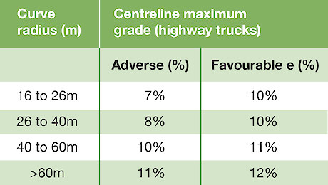
The table below indicates the recommended maximum grade for curves of different radius. These apply to New Zealand on-highway legal log trucks and are a guide only. Steeper grades on curves may result in loss of traction of the inside driver wheels because the effective road gradient on the inside of a small radius curve will be steeper than the centreline gradient. Also, steeper adverse loaded grades on curves may result in loss of traction of the outside driver wheels because of the effect of the weight of the trailer on the turning truck. The trailer tends to pull the weight off the truck back towards the trailer and off the outside driver.
Recommended grade limits Sight distance should also be considered when designing and laying out the road; traffic must have adequate time to see oncoming vehicles or obstacles and safely stop. This is particularly important on one-lane roads where the driver does not have adequate space to take evasive action. In some instances, it may not be practical to improve sight distance so other methods of driver awareness or education needs to occur. For example, posting speed limit signs or simply warning of poor visibility. In all cases, vehicles travelling with minimal sight distance must travel at a speed that allows them to stop in half the visible sight distances, irrespective of what mitigation measures are used to avoid a collision.
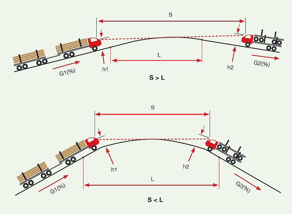
Sight distance is limited by either the vertical (cannot see over a rise) or horizontal alignment (cannot see around the corner). Sight distances are calculated from both alignments and the shorter of the two distances is the limiting factor.
Design sight distances must be maintained over the period of operational use of the road as required by Worksafe’s Approved Code of Practice for Safety and Health in Forest Operations. The chart below indicates the sight distance for a crest vertical curve. If the sight distance is less than the required stopping distance, then either the design must be altered, or other provisions must be made to prevent an accident. It is common practice to manage a collision hazard on active harvesting roads, by ensuring all vehicles maintain radio communications with any moving vehicle, reporting position and direction of travel. Other mitigation measures may include having one-way circulation on roads or applying maximum speed limits.
Vertical curve sight distance examples
If more detail is required, the Unsealed Roads Manual Guidelines to Good Practice, ARRB Transport Research (2009) provides equations where sight distance can be calculated.
The following, in order of preference, are ways to improve vertical alignment and sight distance:
- Re-design the vertical curve, that is, make the vertical curve length longer and/or reduce the grades
- Widen the road to two lanes, and place ‘keep left’ signs. Note that this measure provides limited protection against obstacles on the road
- Place a warning sign to reduce traffic speed, for example, 30 km/hr restriction.
The following, in order of preference, are ways to improve horizontal alignment and sight distance.
- Re-design the horizontal curve, for example increase the curve radius
- Clear the edge of road to increase the sight distance, for example, widen the cut bank, remove trees or vegetation
- Widen the road to two lanes and place ‘keep left’ signs. Note that this measure provides limited protection against obstacles on the road
- Place a warning sign to reduce traffic speed, for example, 30 km/hr restriction.
Sight distance on crest vertical curves (h1=1.5m & h2=0.2m) The above graph can be used to estimate the available sight distance (Source: Austroads 1993: Rural Road Design)
Estimating sight distance on a horizontal curve The chart above shows sight distance for horizontal alignment. Again, for more detailed calculations use the ARRB (2009) reference
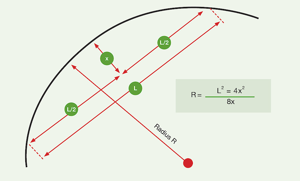
Calculating the curve radius